1.5 Secondary Development Interfaces
No. |
Interface Type |
Interface Name |
X2 Ultra |
X2 Ultra(new version) |
X2 EDU |
|---|---|---|---|---|---|
1 |
RJ45 |
1000 Base-T |
Gigabit Ethernet, accessible to Orin NX and RK3588 |
Gigabit Ethernet, accessible to Orin NX and RK3588 |
Gigabit Ethernet, accessible to RK3588 |
2 |
RJ45 |
1000 Base-T |
Gigabit Ethernet, accessible to Orin NX and RK3588 |
Gigabit Ethernet, accessible to Orin NX and RK3588 |
N/A |
3 |
XT30UPB-F |
12V Power |
12V/3A power output |
12V/3A power output |
12V/3A power output |
4 |
XT30UPB-F |
48V Power |
48V/5A power output |
48V/5A power output |
48V/5A power output |
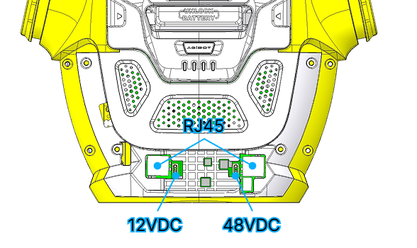
AgiBot X2 Ultra Secondary Development Interface Layout Diagram
Note
The diagram above shows the interface layout of the X2 Ultra. Interface positions on the X2 Ultra(new version) and X2 EDU may differ from the diagram; refer to the actual robot.
The USB interfaces commonly used for secondary development are not covered in this section. Their number and type vary considerably across versions (the X2 Ultra(new version) has dropped Type-A interfaces); see User Debug Interfaces for details.