5.4.1 Sensor Interfaces
The sensor interfaces provide data access and control for the robot’s various sensors, including cameras, IMUs, LiDAR, and touch sensors.
Core Features
Vision Sensors
RGB Camera: Captures color images
Depth Camera: Provides depth information
Camera Intrinsics: Retrieves calibration parameters
Pose Sensors
IMU Data: Acceleration, angular velocity, and attitude angles
Gyroscope: Measures angular velocity
Accelerometer: Measures acceleration
Environmental Perception Sensors
LiDAR: Provides point cloud data
Touch Sensors: Tactile feedback
Standard Sensor Messages
Most sensor interfaces use the standard message types defined in ROS sensor_msgs:
Sensor Data Type |
Message Definition |
|---|---|
Camera intrinsics |
|
Raw image |
|
Compressed image |
|
IMU data |
|
LiDAR point cloud |
|
GNSS positioning data |
IMU Topics
Includes a chest IMU and a torso IMU, both on the Motion Control Computing Unit (PC1).
You can also use the IMUs integrated in LiDAR, RGB-D camera, and stereo camera.
Topic Name |
Data Type |
Description |
QoS |
Frequency |
|---|---|---|---|---|
|
|
Chest IMU data |
|
500Hz |
|
|
Torso IMU data |
|
500Hz |
|
|
LiDAR IMU data |
|
200Hz |
|
|
RGB-D camera IMU data |
|
200Hz |
|
|
Stereo camera IMU data |
|
200Hz |
Note
IMU field usage notes:
frame_id: the
header.frame_idof the chest and torso IMUs is fixed tobase_linkand identical for both; distinguish the data source by topic name.Covariance: the
orientation_covariance,angular_velocity_covariance,linear_acceleration_covariancefields are not provided (all zeros); do not rely on covariance data.Timestamp: The
header.stampof the chest and torso IMUs is the robot receive time, not the sensor sample time; time-sensitive applications (e.g. sensor fusion) should account for serial transmission delay.Motion-control dependency: IMU data is a required input for the motion control system; loss of IMU data (serial failure or
hal_imuprocess not running) will prevent the robot from moving.Extrinsics: the rotation matrix from the IMU to the robot base link is in Factory Calibration Parameters
Head Touch Status Topic
The touch sensor is located on the Interaction Computing Unit (PC3) and supports the following features:
Access low-level touch events and raw samples
Disable the built-in “head pat” skill (to be enabled)
Topic Name |
Data Type |
Description |
QoS |
Frequency |
|---|---|---|---|---|
|
|
Head touch status |
|
100Hz |
TouchStateros2-msg @ hal/msg/TouchState.msg# Head touch status # Topic: /aima/hal/sensor/touch_head MessageHeader header # Message header uint8 event_type # Touch event (0-unknown, 1-idle, 2-touch) uint32[8] data # Raw sensor values for 8 channels (reserved) uint32[8] threshold # Touch thresholds for 8 channels (reserved) bool[8] is_touched # Touch state of 8 channels (reserved)
Rear RGB Camera Topics
The rear RGB camera is on the development compute unit (PC2) and can be used for visual localization assistance and semantic scene understanding.
Raw image bandwidth is about 90 MB/s — use only on the same compute unit, do not subscribe across units.
Topic Name |
Data Type |
Description |
QoS |
Frequency |
|---|---|---|---|---|
|
|
Camera intrinsics |
|
1Hz |
|
|
Raw image |
|
10Hz |
|
|
Compressed image |
|
10Hz |
Note
Rear camera image resolution and encoding:
X2 Ultra: 2064×1552, RGB8 encoding
X2 Ultra(new version): 2048×1536, RGB8 encoding
Compressed image: JPEG encoding (using Jetson hardware encoder)
Installation orientation: The rear RGB camera on the X2 Ultra(new version) is rotated 90 degrees. If your application is affected, refer to Rear Head Monocular Camera Data Subscription to read the hardware version flag and automatically determine whether rotation compensation is needed.
Field of view obstruction: The rear RGB camera’s field of view is partially obstructed by the handle behind the robot’s neck. If your algorithms are affected by this, refer to Rear Head Monocular Camera Data Subscription for mask preprocessing of images.
Obstructed view of Rear RGB Camera on default head posture:
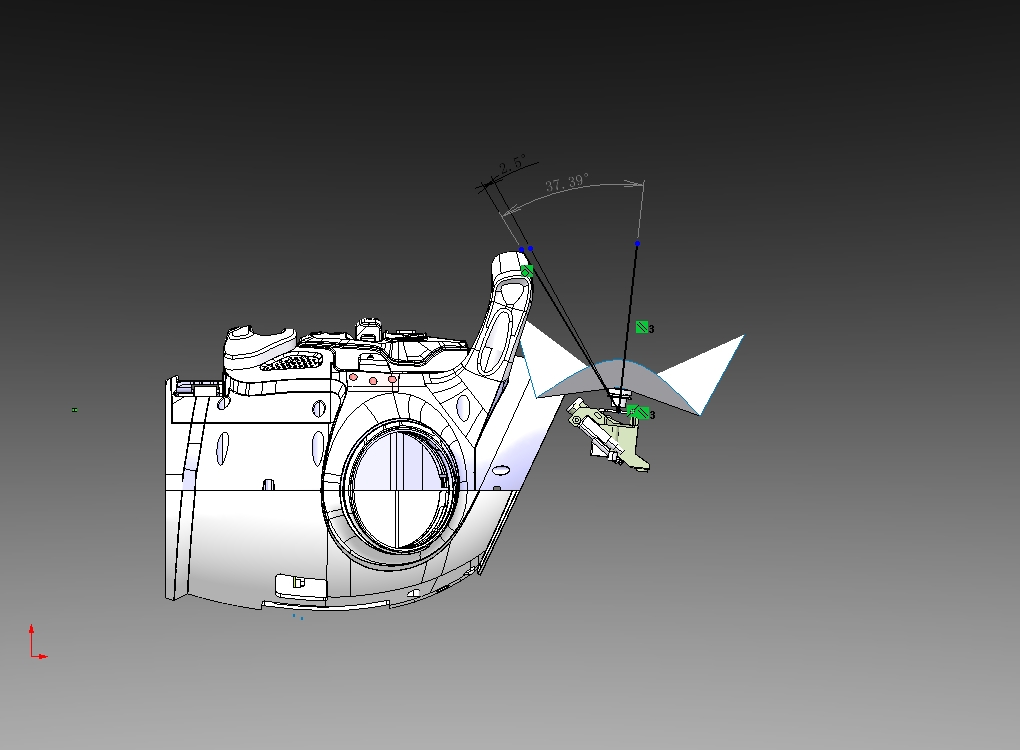
Rear RGB Camera - Obstructed View Diagram
Stereo Camera Topics
The stereo camera is on the development compute unit (PC2) and can be used for stereo vision, teleoperation, obstacle perception, object recognition, VIO SLAM, VLA and more.
Raw image bandwidth is about 90 MB/s per eye — use only on the same compute unit, do not subscribe across units.
Topic Name |
Data Type |
Description |
QoS |
Frequency |
|---|---|---|---|---|
|
|
Left camera intrinsics |
|
1Hz |
|
|
Left raw image |
|
10Hz |
|
|
Left compressed image |
|
10Hz |
|
|
Right camera intrinsics |
|
1Hz |
|
|
Right raw image |
|
10Hz |
|
|
Right compressed image |
|
10Hz |
Note
Stereo camera frame_id notes:
Left:
stereo_head_front(stereo reference frame; stereo extrinsics published via/tf_staticuse this frame as parent)Right:
stereo_head_front_right
The left camera’s frame_id is asymmetric with the _left suffix in the topic namespace. This is because the left camera serves as the stereo vision reference frame (containing the IMU and baseline extrinsics parent frame). Users should note this difference when performing tf integration or stereo epipolar geometry calculations.
Stereo camera image resolution and encoding:
X2 Ultra: 2064×1552, RGB8 encoding
X2 Ultra(new version): 2048×1536, RGB8 encoding
Compressed image: JPEG encoding (using Jetson hardware encoder)
Camera resolution may vary across hardware/software versions. Users should always read the actual resolution from the width and height fields of the camera_info message and avoid hardcoding image dimensions.
RGB-D Camera Topics
The RGB-D camera is on the development compute unit (PC2) and can be used for object detection, spatial obstacle avoidance, and semantic environment understanding.
Raw image bandwidth is about 80 MB/s per stream — use only on the same compute unit, do not subscribe across units.
Topic Name |
Data Type |
Description |
QoS |
Frequency |
|---|---|---|---|---|
|
|
RGB intrinsics |
|
30Hz |
|
|
Raw image |
|
30Hz |
|
|
Compressed image |
|
30Hz |
|
|
Depth intrinsics |
|
30Hz |
|
|
Depth image |
|
30Hz |
|
|
IMU data |
|
200Hz |
Note
Depth camera frame_id notes:
Images and camera intrinsics: frame_id is
rgbd_head_frontImages and camera intrinsics: frame_id is
rgbd_head_frontIMU data: frame_id is
camera_gyro_optical_frame(IMU’s own coordinate frame)
RGB and depth images share the same frame_id (rgbd_head_front); distinguish them by topic name when subscribing. The image and IMU frame_id values differ — mind the coordinate frame when doing sensor fusion or TF transforms.
Image resolution and encoding:
RGB image: 1280×720, RGB8 encoding
RGB compressed image: The camera directly outputs compressed images (MJPEG format)
Depth image: 1280×720, 16UC1 encoding (uint16, pixel value is depth distance in millimeters)
Depth-to-RGB alignment: depth and RGB pixels do not correspond one-to-one (hardware D2C alignment is disabled). The camera module publishes a static transform between the two via /tf_static, which users can use to register depth to RGB in the application layer:
/tf_statictransform: parent framergbd_head_front(color image), child framergbd_depth_head_front(depth image), i.e. the pose of the depth camera frame relative to the color camera frame
Use the depth camera intrinsics in depth_camera_info to convert depth pixels to 3D points in the depth camera frame, then apply the /tf_static transform to convert them to the color camera frame, and finally project them onto the color image plane using the color camera intrinsics in rgb_camera_info. Camera intrinsics and base-to-camera extrinsics are available at Factory Calibration Parameters.
Frame synchronization: RGB and depth frames are published independently and are not synchronized. If frame-level time alignment is needed (e.g., for SLAM or 3D reconstruction), timestamp matching must be performed at the application layer.
LiDAR Topics
Provides LiDAR point clouds and LiDAR-integrated IMU data for obstacle avoidance and SLAM/localization.
The LiDAR is on the development compute unit (PC2) with data bandwidth on the order of 10 MB/s — cross-unit subscriptions are not recommended.
Topic Name |
Data Type |
Description |
QoS |
Frequency |
|---|---|---|---|---|
|
|
LiDAR point cloud |
|
10Hz |
|
|
LiDAR IMU data |
|
200Hz |
Point cloud data notes:
frame_id:
lidar_chest_front(sensor native coordinate frame, no axis reordering)Point type:
PointXYZIRT— includes x/y/z coordinates, intensity (reflection intensity), ring (beam index), timestamp (relative timestamp)Distance unit: meters (resolution 0.005m), blind zone 0.1m; maximum detection range depends on ambient lighting and target reflectivity (e.g., ~30m under 10% NIST 100klux sunlight conditions)
LiDAR IMU notes:
frame_id:
lidar_imu_chest_front(different from the point cloud’slidar_chest_front)When the module first receives a device information packet, it automatically publishes the IMU→LiDAR static transform to
/tf_staticUsers performing sensor fusion should use this frame_id and the tf_static transform
GNSS Topic
The GNSS module provides positioning data for outdoor localization, navigation, and similar scenarios.
Topic Name |
Data Type |
Description |
QoS |
Frequency |
|---|---|---|---|---|
|
|
GNSS positioning data (latitude, longitude, altitude) |
|
1Hz |
Note
NavSatFix key field notes:
status.status (fix status):
0(STATUS_FIX): Valid fix1(STATUS_SBAS_FIX): Augmented fix (SBAS, Satellite-Based Augmentation System)-1(STATUS_NO_FIX): No fixUsage tip:
status >= 0indicates a valid fix
status.service (satellite system):
Fixed to
1(SERVICE_GPS, Global Positioning System) in current firmwareNote: This field does not reflect the actual satellite system in use; for reference only
position_covariance (position accuracy):
3×3 covariance matrix [m²]; diagonal elements represent uncertainty in East, North, and Up directions
Value interpretation: Lower values indicate higher accuracy; typical values of 1-10 m² indicate good accuracy
Estimated based on satellite geometry (HDOP, Horizontal Dilution of Precision)
covariance_type (accuracy type):
1(COVARIANCE_TYPE_APPROXIMATED): Estimated from satellite geometry (used by current firmware)0(COVARIANCE_TYPE_UNKNOWN): No accuracy information
Code Examples
For detailed code samples and explanations, see:
IMU Data Subscription: IMU Data Subscription IMU Data Subscription
LiDAR Data Subscription: LiDAR Data Subscription LiDAR Data Subscription
GNSS Data Subscription: GNSS Positioning Data Subscription GNSS Positioning Data Subscription
Head Touch Sensor: Head Touch Sensor Data Subscription Head Touch Sensor Data Subscription
Camera Data Subscription (depth/stereo/rear): Camera Streaming Example Collection Camera Streaming Example Collection
Take Photo: Take Photo Take Photo
Safety Notes
Attention
For high-bandwidth raw camera streams, do not subscribe across compute units; this may destabilize the system and create safety risks.