1.8 Coordinate System
When all joint angles are at their zero positions, the coordinate systems of each robot component are distributed as shown in the figure below. Red indicates the X-axis, green indicates the Y-axis, and blue indicates the Z-axis.
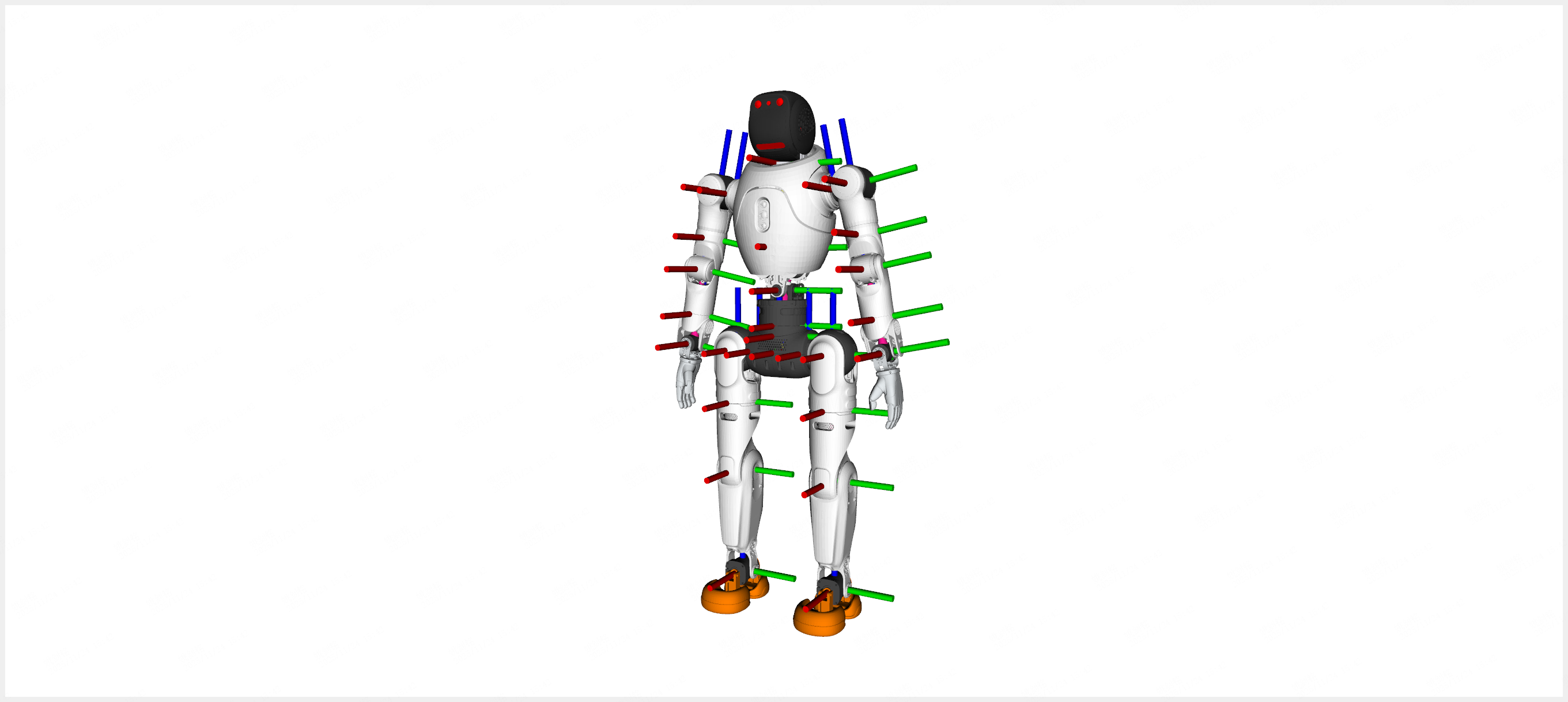
Coordinate System Diagram
1.8.1 URDF and Factory Calibration
Robot coordinate-system data falls into two categories with different purposes:
URDF (
x2_ultra.urdf, available via the SDK): describes the joint-chain kinematic model, including link geometry, joint axes and limits, and rigid transforms between links. The coordinate frames are nominal design values, identical across the same model, used for kinematic solving, visualization (RViz/Foxglove), and joint-space planning.Factory calibration (see below): records the measured mounting pose of each sensor relative to the base link and the camera intrinsics; each robot is different, used for sensor fusion and multi-sensor coordinate transforms.
The two are complementary: the URDF provides the joint-chain frames (nominal), while factory calibration provides the measured sensor poses in the base-link frame (individual variation).
1.8.2 Factory Calibration Extrinsics
Each sensor on the robot is calibrated at the factory. The calibration results are stored on the development unit (PC2) at:
/agibot/data/param/protected/factory_calib/factory_calibration_params.yml
This YAML file contains the extrinsics of each sensor relative to the robot base link, as well as the camera intrinsics and distortion coefficients. Use this file as the authoritative source for sensor fusion and multi-sensor coordinate transforms.
Note
R_baselink_sensor is the 3x3 rotation matrix from base link to sensor (row-major 9-element array); t_baselink_sensor is the translation vector from base link to sensor, in meters.
The file is organized by sensor section; each section’s meaning is as follows:
Section |
Sensor |
Calibration content |
|---|---|---|
|
Waist IMU |
Base->IMU rotation matrix |
|
Chest IMU |
Base->IMU rotation matrix |
|
Rear RGB camera |
Intrinsics, distortion, base->camera rotation+translation |
|
Stereo left camera |
Intrinsics, distortion, left-right extrinsics, base->camera rotation+translation |
|
Stereo right camera |
Intrinsics, distortion |
|
Head depth camera RGB |
Intrinsics, distortion, base->camera rotation+translation |
|
Chest LiDAR |
Base->LiDAR rotation+translation |
Field meanings:
Field |
Applicable sensors |
Meaning |
|---|---|---|
|
All |
Calibration timestamp |
|
All |
Head joint angles during calibration (unit: rad) |
|
All |
Base->sensor 3x3 rotation matrix (row-major 9 elements) |
|
Camera / LiDAR |
Base->sensor translation vector (unit: m, 3 elements) |
|
Camera |
Camera model: |
|
Camera |
Calibration resolution |
|
Camera |
3x3 intrinsic matrix (fx, fy, cx, cy) |
|
Camera |
Distortion coefficients (k1, k2, p1, p2, k3) |
|
Stereo left camera |
Left->right camera 3x3 rotation matrix |
|
Stereo left camera |
Left->right camera translation vector (unit: m) |
Warning
This file contains factory calibration results – do not modify. Calibration parameters are bound to the individual robot; different robots have different parameters.